iTaSC user guide
Creating an iTaSC application
The iTaSC main manual is currently in pdf version, until the wiki version is finished.Computation
See pdf manualConfiguration and coordination: Skills
What is a skill?
A Skill is a specific combination of the configuration and coordination of Tasks. An iTaSC skill is implemented in the framework using the Lua based rFSM Finite State Machine (FSM) engine. The following design rules should be/are applied:- Event driven: Events trigger the FSMs to transition from one state to another.
- Each FSM should be designed such that it is framework independent (e.g. from OROCOS RTT).
- Each FSM is loaded in a Supervisor component, that contains the OROCOS (RTT) specific parts of the FSM.
The 3 FSM levels
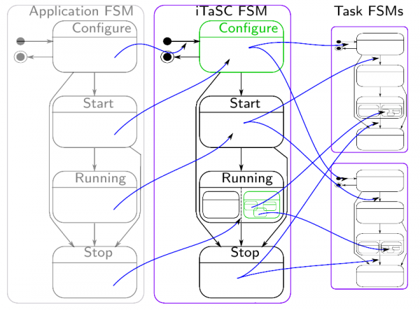
There are 3 levels of FSM for an iTaSC application (hierarchical state machine):- Application: The state machine of this level takes care of the behavior of the whole system: it configures and coordinates components not part of iTaSC (e.g. hardware interfaces and trajectory generators) and iTaSC as one composite component. The application developer takes care of the first part and sends (the fixed set of) events to configure and coordinate the iTaSC composite component. The transitions of the application state machine are always triggered by the a “done” signal raised by the iTaSC FSM (i.e. “e_ITASCConfigured” event, see 1.4) and additionally by user defined events that are raised by non-iTaSC components (i.e. hardware ready).
- iTaSC: The state machine of this level configures and coordinates the behavior of iTaSC components. It has a fixed structure, leaving two parts to be specified by the application developer ("user"). Firstly, the user must specify the description of the scene and the composition of the kinematic loops in the configuration file (“itasc_configuration.lua”). This file DOES NOT describe the actual behavior of the task but the components which are involved (Composition). Secondly, the subFSM part of the running state must be defined. The running state of the state machine is composed by two parts: the first coordination part is fixed and takes care of running all iTaSC components in the right order (actually making iTaSC components running as a composite component, from the user perspective), the second, the subFSM part (highlighted in green in fig The 3 FSM levels), specifies the high level workflow of the task. This second sub-state machine defines the transitions between the tasks.
- Task: The state machine of this level contains a more concrete coordination of the task: while the previous level abstracts from task specifics, here, the actual triggers to change the characteristics of the iTaSC components must be implemented (i.e. assignment of property values, etc.) see 1.5 for an example.
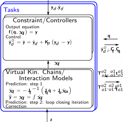
These levels are not only present on the configuration/coordination but also on the computational level (see slides). As hinted before your application FSM will only 'see' the components 'outside' iTaSC (robot drivers, sensor components...) and iTaSC as one composite component. Similarly, the iTaSC FSM 'sees' a task as one entity. Section 'The sub-FSMs of the running state', gives a good example/effect of this distinction.
As a result of the 3 levels, your application is always in 3 states: one for each level.
 The 3 FSM levels
The structure of a FSM
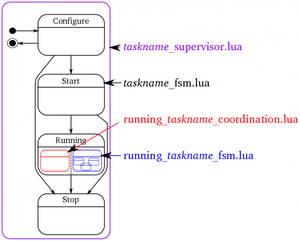
In the standard implementation, a FSM of a certain level consist of 3 files, e.g. for a task:- taskname_fsm.lua: This is the actual state machine
- running_taskname_coordination.lua: This is the coordination part of the running state ensuring that the iTaSC algorithm is executed in the right order.
- running_taskname_fsm.lua: This is the sub-FSM part of the running state. This part should be edited to implement the behavior of the running application.
The coordination and FSM part of the running state are executed sequentially. The full FSM is loaded in a supervisor component: taskname_supervisor.lua
On the iTaSC level, composite_task_fsm.lua is used instead of running_itasc_fsm.lua, to highlight its meaning. There is also an additional file: itasc_configuration.lua, which is part of the configuration state of the itasc_fsm.lua.
 FSM structure
The state machine implemented in name_fsm.lua is a composite state machine, consisting of two states:
- NONemergency state: is a subFSM, containing the actual state machine, as shown in the figure above,
- emergency state: an 'e_emergency' event is fired by one of the FSMs or components, in case of a failure. This event is caught by all state machines, causing them to transition to the emergency state, leaving whatever state the NONemergency sub state machine is in.
This structure can be found in all statemachines of all levels (except for the application FSM, where the division of the running state is not (always) necessary).
The event-transition flow
In order to get your application running, the application has to be configured and started. After running, you also want it to stop (. Moreover, these actions should happen in a coordinated way.As explained above, there are three levels: application, iTaSC and task: each of which makes abstraction of the level below it. As a result, events are propagated down the hierarchy to take effect and responses are sent back up, to acknowledge execution. The design of the Application and Task FSM should comply with the same rationale (i.e. each transition is triggered by the lower level FSM). The standard event-transition flow consists of:
- (every component initializes at start-up, without the need for an event)
- the application level FSM transitions to the configuring state, after initialization. In this state, all application level components are configured and an event is sent ("e_configITASC"), to which the iTaSC level FSM will react by transitioning to the configuring state.
- The iTaSC level FSM, now in its configuring state, will on his turn configure the iTaSC level components and send an event ("e_configTasks") that triggers the tasks to get to the configuring state.
- the task level FSMs (also in the configuring state now) on their turn will configure the task level components. After successful completion, the task level FSMs will transition to the configured state and send out an event to acknowledge this completion of the configuration.
- When all tasks and iTaSC level components indicated a successful configuration, the iTaSC level FSM will transition to the configured state and send out an "e_ITASCConfigured" event.
- When all application level components indicate a successful configuration and this "e_ITASCConfigured" event is received, the application level FSM will transition to the application configured state.
- After an event triggering the transition of the application level FSM from the configured state to the starting state (in the most examples, just an e_done = completion of the configured state actions), a similar event-transition flow follows for the starting-started states.
The flow for the stopping-stopped states is also similar. The running states are different in the sense that there is no 'ran state': the state machines will stay in the running state until they are stopped.
The sub-FSMs of the running state
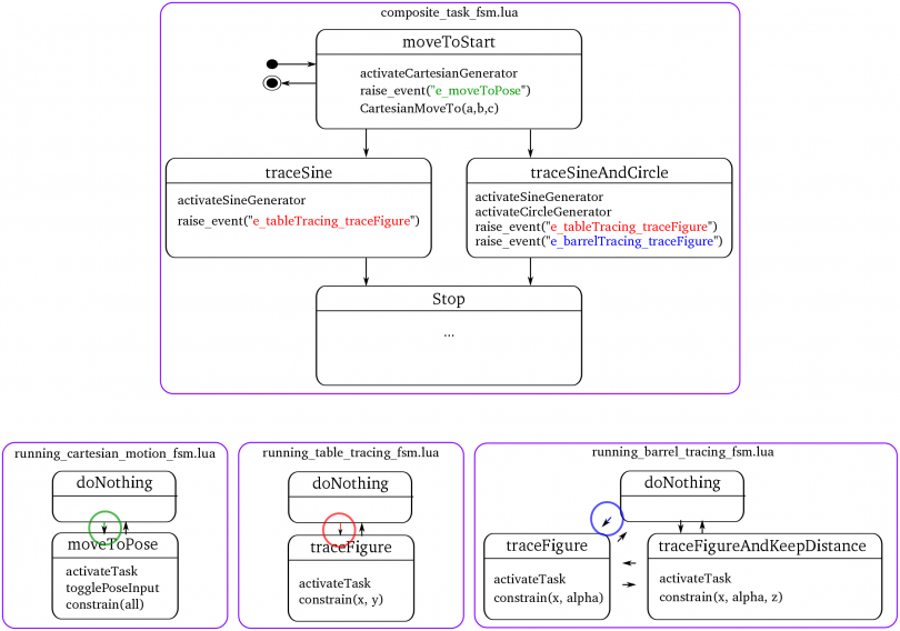
The actual behavior of the application at runtime, is governed by the sub state machines of the running states of each level, which form a hierarchical state machine. The idea is that a high(er) level description is implemented in the composite_task_fsm.lua. The actual behavior of the individual tasks is governed by a separate sub-state machine for each task, running_taskname_fsm.lua. In other words: the composite_task_fsm coordinates the behavior between the different tasks. The running_taskname_fsm coordinates the behavior of the task.The following figure gives an example of the composite task and tasks in case of the simultaneous laser tracing on a table and a barrel example, used in previous paragraphs. The goal is to (in this order):
- Move to a certain starting pose (position and orientation)
- Trace a sine on a table and a circle on a barrel, if a barrel is detected
- Trace a sine on a table, if no barrel is detected.
In the figure, a (sub-)FSM is represented by a purple rounded box, a state by a rounded black box and a possible state transition by an arrow. State transitions are triggered by an event or combination of events. The state transitions of the task subFSMs, indicated by a colored arrow and circle, are caused by the event with the corresponding color, fired in the composite_task_fsm.lua.
To prevent overloading the figure, only a limited number of actions is shown, e.g. only the entry part of the state and not the exit part (which will, e.g. deactivate the trajectory generator and tasks which were activated).  SubFSMs of the running state
The composite state of the example in the figure consists of 4 states.
- The initial state is the "moveToStart" state,
- which activates the needed trajectory (actually a set point generator),
- raises an event to cause the needed cartesian_motion task to reach a "moveToPose" state
- and then calls the Lua function "CartesianMoveTo()", which is implemented in the itasc_supervisor.lua (no RTT specifics in the statemachine, remember!).
- Depending on the presence of a barrel (somehow detected, and notified to the FSMs by an event), there is a state transition to the "traceSine" or "traceSineAndCircle" state, after completing the "moveToStart" movement (notified by another event). Either of this states will
- activate the right trajectory/set point generator,
- send an event that causes the running_table_tracing_fsm.lua subFSM of the table_tracing task (and running_barrel_tracing_fsm.lua subFSM of the barrel_tracing task) to transition to a traceFigure state.
- After completion of the tracing task (or another stop-transition causing event), the composite state machine will reach a stop(ped) state.
As can be seen, the composite task FSM just sends an event to trigger the task subFSMs to reach the appropriate state. The task subFSM will take care of task specific behavior, e.g.
- selecting the feature coordinates to constrain
- activate these constraints
- change the weight of a specific constraint
- alter control parameters (gains...)
- ...
Doing so, the tasks can be easily adapted/ swapped/ changed/ downloaded.
Note: The names of the tasks are specific; i.e. they are the names of the components that are used for the tasks. The name of the task package will be more general, e.g. xyPhiThetaPsiZ_PID task (named after the structure of it's VKC and controller type). Cfr. class - object of object oriented programming.
Event types
There are currently three types of events, that differ in how they are communicated (see also 'Communication') and treated:- Common events: events that 'can wait' to be handled, together with other events, in the next update/iteration, e.g. "e_startItasc" event,
- Priority events: events that can't wait to be handled in the next update, e.g. "e_emergency" (fired in case of a failure),
- Trigger events: events that trigger other state machines or components, typically used to ensure an algorithm distributed over multiple FSM is executed during the correct time step and in the right order, e.g. "e_triggerTasks", fired by running_itasc_coordination.lua.
Composition
Communication
All communication of data, including events, is done over Orocos ports. The FSMs communicate their events by the event ports of the components they are loaded in (supervisors). There are separate ports for each type of event (in and output event-port for each type):- Common events: Communicated over a buffered connection
- Priority events: Communicated over a buffered connection on event-triggered ports
- Trigger events: Communicated over a non-buffered connection on event-triggered ports
Conventions
To automate the majority of the scripting, the following conventions are taken into account in the examples:- the components and scripts have the task name in their names, e.g. for cartesian_motion
- package name: cartesian_motion
- component names: VKC_cartesian_motion.hpp
- script names: cartesian_motion_supervisor.lua
- For conformity it is advised to use lower case names with underscores to separate words.
| Attachment | Size |
|---|---|
| iTaSC_Manual.pdf | 396.63 KB |
How to create a new task?
Please read the iTaSC_Manual first, to get acquainted with the iTaSC terminology and structure. A task is the combination of a virtual_kinematic_chain and a constraint/controller. In the iTaSC software, it is a (ROS-)package that contains:
- src/ containing the source code of the components (C++)
- VKC_taskname.hpp/cpp
- CC_taskname.hpp/cpp
- cpf/ containing the property files for the components and FSM's
- scripts/ containing the FSM's and components in a LUA implementation
- taskname_supervisor.lua: the supervisor orocos-component, containing the Orocos specific code, eg. ports to recieve/send events on...
- taskname_fsm.lua: the finite-state machine containing the actual Skill
- running_taskname_coordination.lua: the sub-finite-state machine of the running state of the task, containing the coordination part of the task, it determines what the task part of the iTaSC algorithm should do and in which order
- running_taskname_fsm.lua: the sub-finite-state machine machine of the running state of the task, determining the actual actions of the task (when to enable the task, when to change weights...)
- launch/ containing eventual ROS launch files
The running_taskname_coordination.lua and running_taskname_fsm.lua, are sub-FSM's of the running state of the task (defined in taskname_fsm.lua). They are executed sequentially, first the coordination part, then the FSM part.
Getting started
A tasks consists of a Virtual Kinematic Chain (VKC) (except for constraints on joints only) and a Constraint Controller (CC).Virtual Kinematic Chain (VKC)
A VKC inherits from VirtualKinematicChain.hpp in the itasc_core unary stack, which serves as a basic template.Important are the expected reference frames and points for the data on following ports. (o1=object 1, o2= object 2)
- Inputs
- $T_{o1}^{o2}$ = RelPose(o2|o2,o1|o1,o1) = pose of o2 on body o2 wrt. o1 on body o1 expressed in o1
- $_{o1}^{o1}t_{o2}^{o1}$ = RelTwist(o1|o1,o1,o2) = twist with ref.point o1 on object o1 expressed in o1
- Outputs
- $T_{o1}^{o2}$ = RelPose(o2|o2,o1|o1,o1) = pose of o2 on body o2 wrt. o1 on body o1 expressed in o1
- $J_{u}\chi_{u}$ =
- $_{o1}^{o2}J_{f o1}^{o1}$ = Jacobian(o1|o2,o1,o1) = ref.point o1 on object o2 expressed in o1
The expected references are also mentioned as comments in the files
Constraint/Controller (CC)
A Constraint/Controller inherits from ConstraintController.hpp in the itasc_core unary stack, which serves as a basic template. task_layout
A full template will be made available soon... At the moment, start from an example... Have a look at the keep_distance task-package (in the itasc_comanipulation_demo stack) as a good example of a task. Special cases are:
- cartesian_motion: This task, defines a virtual kinematic chain with in stead of feature coordinates x,y,z,roll, pitch, yaw, the full pose (KDL::Frame), to enhance efficiency of the code (and prevent singularity problems).A separate port, the ChifT port transfers this data from the VKC to the CC, which should be connected manually at the moment!. ChifT = RelPose(o2|o2,o1|o1,o1) = pose of o2 on body o2 wrt. o1 on body o1 expressed in w
- joint_motion: This task has no virtual kinematic chain, because its output equation is y=q. It constrains only the joint coordinates.
Conventions
To automate the majority of the scripting, the following conventions are taken into account in the examples, which is recommended to do for new tasks too:- the components and scripts have the task name in their names, eg. for cartesian_motion
- package name: cartesian_motion
- component names: VKC_cartesian_motion.hpp
- script names: cartesian_motion_supervisor.lua
- For conformity it is advised to use lower case names with underscores to separate words
How to create a new robot or object?
Should inherit from SubRobot.hpp, which can be found in the itasc_core. This file is a template for a robot or object component. See itasc_robots_objects stack for examples.
As can be seen in the examples, a robot component contains always a KDL::Tree, even if the robot is just a chain. This is to be able to use the KDL::Tree functionality, which is regrettable, not perfectly similar as the KDL::Chain functionality. E.g. tree.getSegment(string name) has a string as input, chain.getSegment(number) has a number as input, but not a string...
How to create a new solver?
Coming soon, have a look at itasc_solvers for examples.